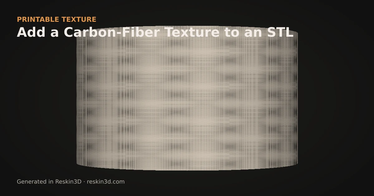
To add carbon-fibre texture to an STL for printing, apply a regular woven height map to selected panels, align its direction, keep the relief shallow and bake it into the mesh.
Understand what an STL can preserve
A photographic carbon-fibre image can look convincing in a renderer while producing a completely smooth print. STL stores triangle geometry, not a reflective material shader. Reskin3D’s Carbon Fiber preset turns the weave structure into physical surface variation that survives export.
This works best on automotive props, electronics panels, drone shells and display parts where visual weave matters more than certified composite behaviour.
Align the weave
Use planar mapping for one panel, cubic mapping for an enclosure or surface mapping for a curved shell. Rotate the pattern so the weave follows a deliberate product axis. Keep infinite variation off because a carbon weave depends on consistent over-under repetition.
Begin near the preset’s 20 mm real-world tile and approximately 0.35 mm depth. If individual bands vanish in the slicer, enlarge the tile; increasing depth alone creates harsher peaks without making bands wide enough for the nozzle.
Set honest expectations
The printed result is monochrome relief. Filament colour, layer orientation and lighting determine the final appearance, and the geometry does not reproduce resin gloss or carbon-fibre strength. Keep the page and any shared model description clear about that distinction.
Three-step workflow
- Select the visible panels while excluding joints and clearances.
- Apply Carbon Fiber, align the weave, and start near a 20 mm tile with 0.35 mm depth.
- Bake, export and confirm both weave directions remain visible in sliced toolpaths.